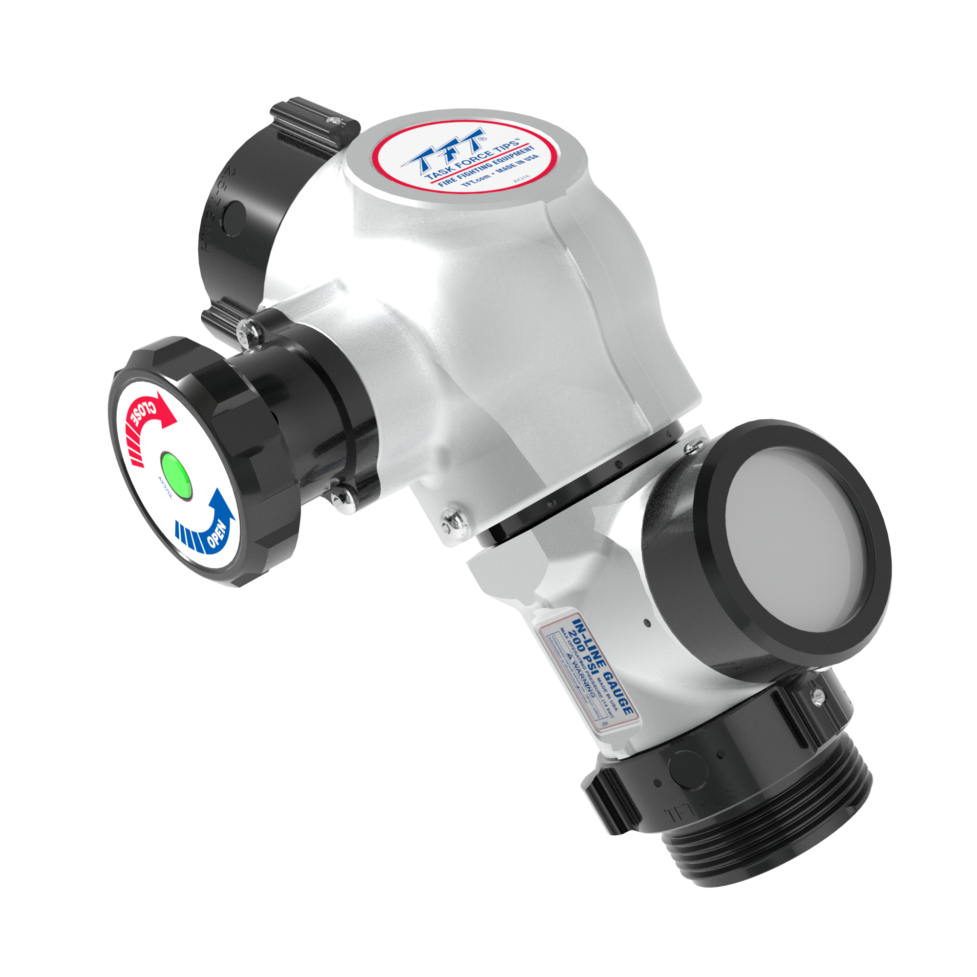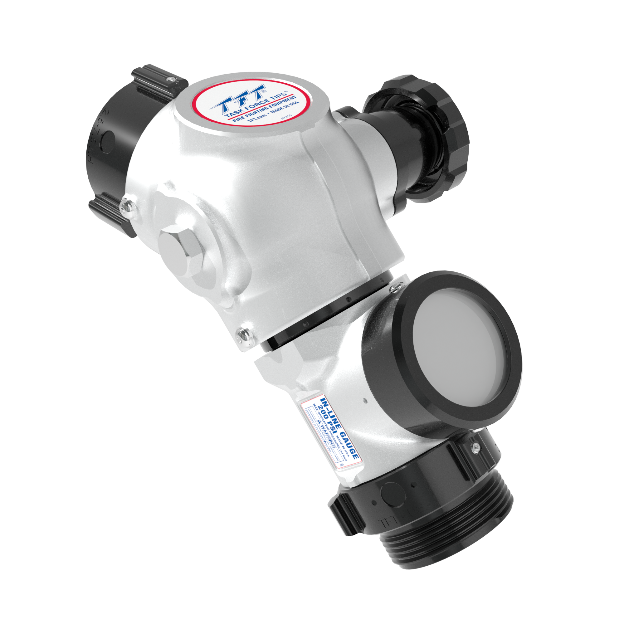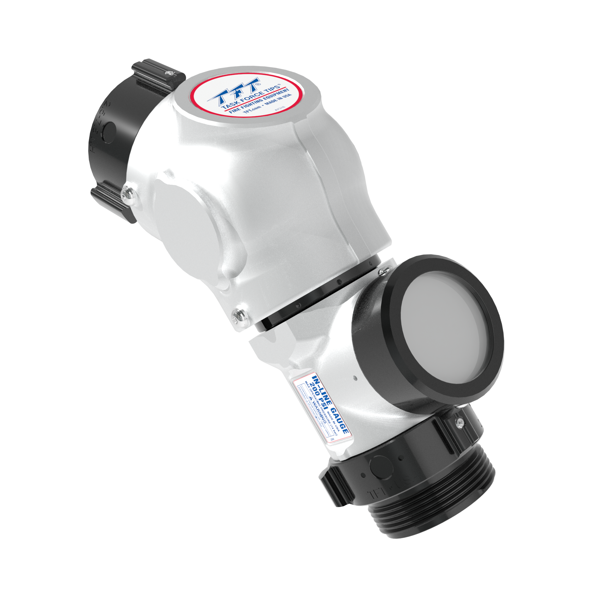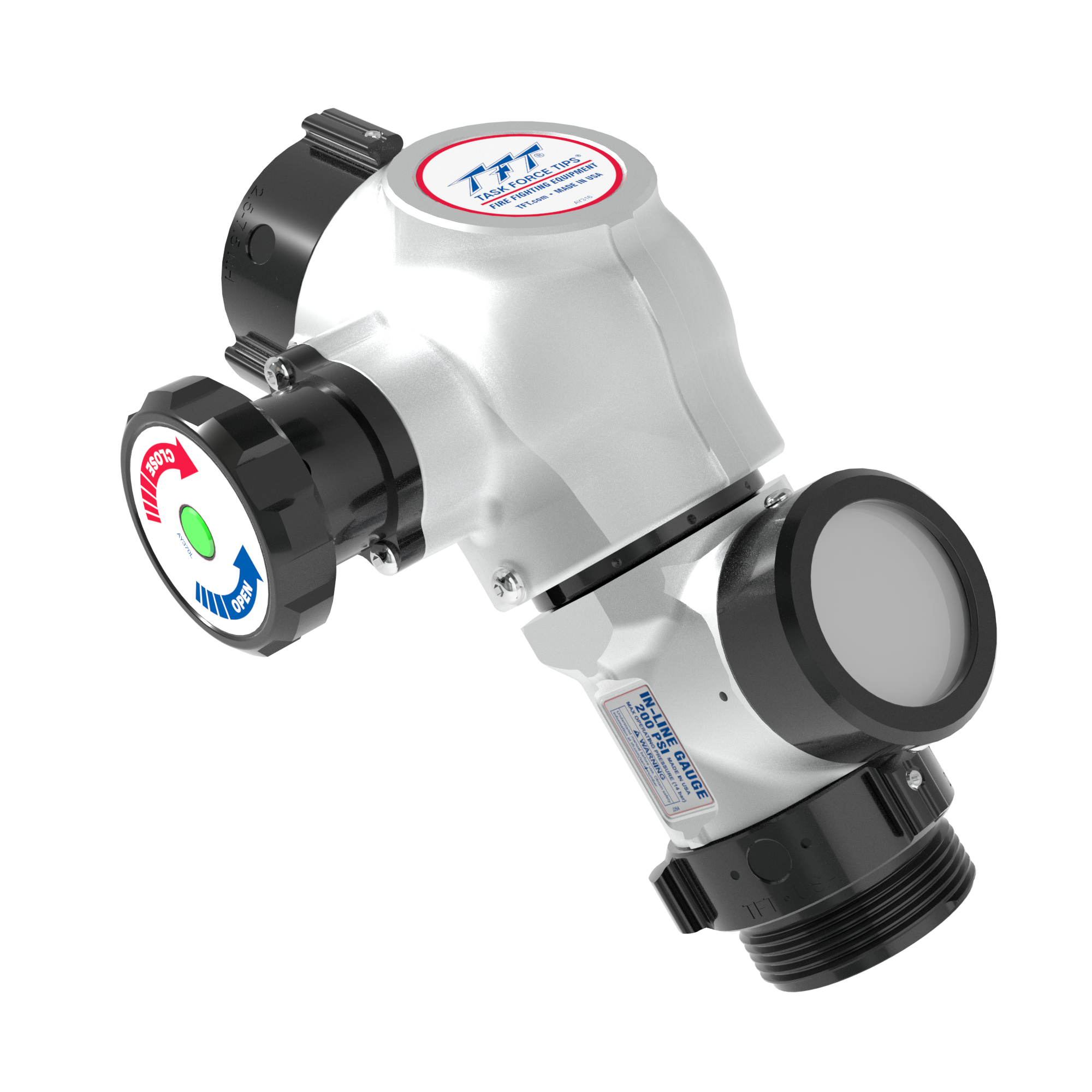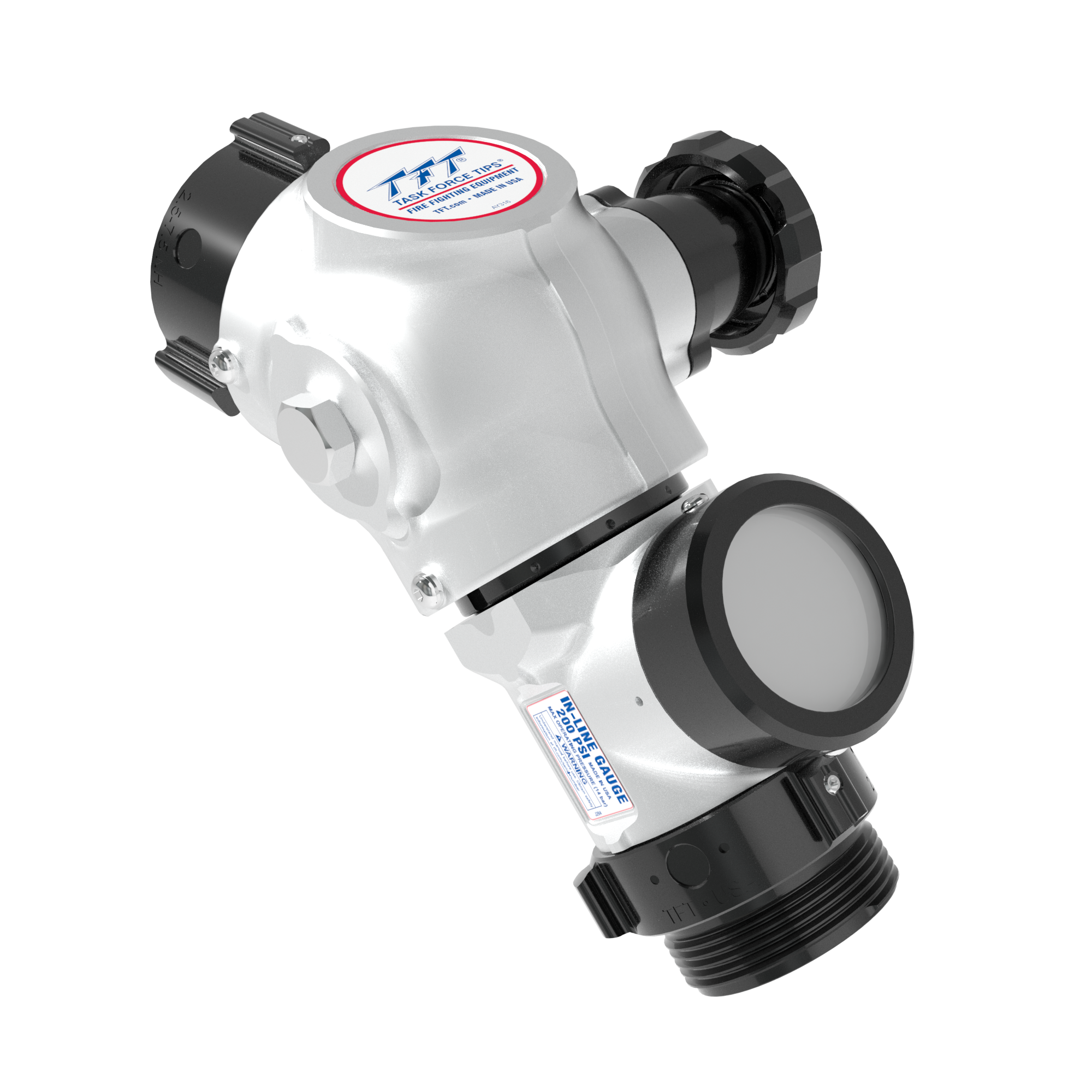















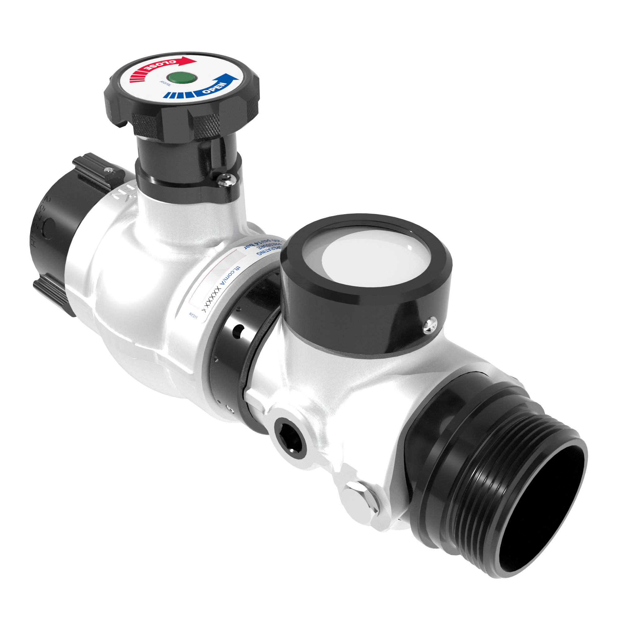
HI-RISE VALVE W/GAUGE 0-300 PSI
$1,699.75
2.5″F SWIVEL ROCKER X PIVOT 2.5″M SLOW CLOSE
All Prices in USD

The Task Force Tips HI-RISE VALVE W/GAUGE 0-300 PSI is engineered for critical water flow management in challenging environments, particularly high-rise fire operations. Designed for precision and reliability, it provides firefighters with essential control and immediate pressure monitoring capabilities at the point of use.
- Integrated Pressure Monitoring: The included 0-300 PSI gauge delivers vital pressure readings instantly, enabling precise hydraulic management for high-rise standpipe systems or attack lines.
- Rapid Control and Durability: Featuring an aluminum ball valve design, operators benefit from quick, positive quarter-turn shut-off and robust construction for demanding fireground conditions.
- Optimized for Portability: At a weight of 9.500 lbs, this 2.5″ (65 mm) valve maintains critical strength while remaining manageable for transport and deployment across multiple floors.
- Secure Coupling: Equipped with a 2.5″ (65 mm) non-full time swivel coupling on Side A, it ensures a secure and stable connection to your hoseline or standpipe outlet.
The deliberate design of this Task Force Tips valve, from its lightweight aluminum body with Stardust Silver finish to the integrated gauge, supports efficient and safe water delivery in complex vertical structures. It is an indispensable component for municipal and industrial departments requiring reliable control and critical pressure feedback during high-rise incidents.
| Shipping Box Dimensions |
18.00 × 12.00 × 8.00 in |
|---|---|
| Weight | |
| Valve Design | |
| Finish | |
| Coupling Size Side A | |
| Coupling Swivel Side A | |
| Material | |
| Coupling Size Side B | |
| Size | |
| Operation Energy Source |
Technical Specifications and Drawings
Instructions For Installation, Safe Operation and Maintenance
- In-Line Pivot Gage and In-Line Gage Manual
- Valve: 2.5inch Quarter Turn Hydrant Valve Manual
- Analog In-Line Gauge Series Manual
- Analog In-Line Gauge Series Manual